VRRP – Virtual Router Redundancy Protocol provides Network failover/redundancy
VRRP (Virtual Router Redundancy Protocol) provides fail-over/ redundancy for critical gateway network components like Routers, L3 Switches, Firewalls/UTM’s, etc. VRRP eliminates single point of failure at the gateway level and in certain network configurations, it can even provide load balancing along with fail-over. Let us learn more about VRRP, in this article.

What is VRRP?
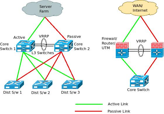
VRRP is the short form for Virtual Router Redundancy Protocol. It provides fail-over / redundancy for Layer-3 based Gateway devices in the network (Routers, Firewalls, UTM, Layer-3 Switches, etc). When the primary gateway device in the network fails, the VRRP enabled pre-configured back-up device takes over quickly to resume the network functions provided by the master gateway device earlier. This way, users don’t experience any disruption of network services.
Generally, one gateway device acts as the primary (through which all the traffic flows) and is the active device. The other back-up gateway device is kept passive (no traffic flows) until the active device fails. So when the primary device fails, the back-up device becomes active and all the traffic starts flowing through it. The master gateway device sends periodic heart beat messages to the back-up devices (generally once in a second) to confirm that it is alive and functioning. Once these messages stop, back-up device takes over.
VRRP is an Industry Standard Open protocol and it is specified in IETF RFC 3768. Since it is a standard, multiple vendor gateway devices can be configured to be a part of the VRRP group. Even multiple types of devices can be configured to be a part of the same VRRP group. For example, the primary gateway device can be a Firewall/ UTM and the back-up device can be a Router, as long as both of them support VRRP.
What is a Virtual Router (or Virtual Gateway)?
A Virtual Router / Gateway is a collection of all the VRRP enabled devices in the same network / subnet. Please keep in mind that there can only be one primary/ master in each network / subnet, but there can be multiple back-up devices (slaves). So, if there are two routers – one primary and one back up, configured for a particular network segment, these two routers together are referred to as ‘Virtual Router’.
All the VRRP enabled individual gateway devices within a particular network are considered to be a single virtual router/ gateway because all of them share the same (virtual) MAC address and IP address. Further, the configuration of the primary (master) gateway device is replicated in the back-up devices, including the VLAN configuration/ forwarding information.
All the gateway devices are configured with individual VRRP priority levels called VRID. The VRID value is between 1 to 255 and the master/ primary device is generally configured with VRID = 255. Upon the failure of the primary device, which ever back up device has the next highest VRID takes over. This provides an order in which the various back-up devices can become active (one by one) without any conflict and hence provides multiple levels of redundancy. Once the primary device is up, the back-up device transfers the control / traffic back to the primary device.
What are the advantages of VRRP?
- VRRP provides fail-over / redundancy at the network gateway.
- There is no single point of failure (due to VRRP) as a back-up device is configured to take over once the primary device fails.
- The fail-over happens quickly (often in a very few seconds).
- Generally, VRRP is employed in Active-Passive (Primary-Backup) configuration. But (as shown below), it can also be configured for Active-Active configuration with load-balancing.
- VRRP is an IETF Open Standard Protocol – So, multiple vendor / multiple type of devices can be a part of the VRRP group.
- There can be multiple back-up devices for the primary gateway device, if required.
Failover/ Redundancy with Load-balancing in VRRP:

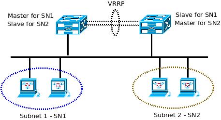
Normally, VRRP is configured between two gateway devices with the primary device in the active state and the back-up device in the passive state. So, the back-up device does not function unless the primary fails. Obviously, this is an issue because back-up device resources are wasted. With some minor redesign (as shown in the above diagram), VRRP can be used to provide load-balancing with both devices in the Active-Active state.
In the above ‘load-balancing in VRRP architecture diagram’ which gives an example configuration of Active-Active load balancing along with fail-over, the network is divided into two subnets (SN1 & SN2). The gateway device on the left is configured as the primary for all traffic from SN1 and the device on the right is configured as back up for SN1. Its the reverse for SN2. So, both the gateway devices are active in this configuration and since the number of systems are divided between SN1 & SN2, traffic is also divided (and load balanced) between the two gateway devices.
From the design perspective, it is also possible to have two separate masters (for SN1 & SN2 respectively) and one common slave device that has interfaces in both the subnets. If either of the master devices fail, the back-up gateway device can provide fail over.
excITingIP.com
You could stay up to date on the various computer networking / enterprise IT technologies by subscribing to this blog with your email address in the sidebar box that says, ‘Get email updates when new articles are published’
Please provide for VRRP configuration.
Thanks,
Rain
I cant understand very well could you show me with configurations and explain it . thanks………………